TOPTECH ELECECTRIC (H.K) INC.,LTD.
1.Torque Motors and Direct Drive Systems
1、Descrition of Torque Motor and Direct Drive Motor

1-1 Torque Motor and Direct Drive Motor
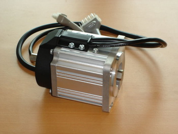
Torque motors are a special class of brushless permanent magnet servomotors. This type of motor is also commonly referred to as a permanent magnet synchronous motor or a brushless DC motor.
1-2 The Direct Drive torque motor is a servo actuator which can be directly attached to the load it drives. It has a permanent magnet (PM) field and a wound armature which act together to convert electrical power to torque. This torque can then be utilized in positioning or speed control systems. In general, Torque Motors referred to Direct Drive DC torque motors, These torque motors are normally deigned and classified as following three different types of operation:
1-2-1 High stall torque for positioning systems
1-2-2 High torque at low speeds for speed control systems, and
1-2-3 Optimum torque at high speed for positioning, rate, or tensioning systems.
2、Advantages and Features of Torque Motor and Direct Drive DC Motor
2-1 Very small electrical time constant, this easily make High dynamic response or fast feedback.
2-2 Big mechanical air gap, It is quite convenient and easy mounting and alignment or simple installing.
2-3 High Efficiency and Reliable Power resulting from the application of RE Magnets.
2-4 Excellent Torque value
2-5 Overall dimensions with a relatively large diameter to length ratio
2-6 Frameless
2-7 Direct drives eliminate the need for gearboxes, worm-gear drives, or other mechanical transmission elements. Motor life sound excellent.
2-8 Big inner diameter is quite advantageous for machine tools construction.
2-9 Wide range of dimensions, Diameters from less than 100mm to greater than 2200mm
2-10 Very low speed and High Torque with excellent accuracy, such as 5-10RPM etc. this is very fitted for telescope application or Radar Systems
2-11 High torque at stall and high dynamic stiffness.
2-12 High accuracy and repeatability
2-13 High Linearity
2-14 High Resolution
2-15 Smooth, Quiet Operation
3、Torque Motors and Direct Drive Motors which Toptech makes
3-1 Frameless BLDC Torque Motor: QTM-FL
3-2 Framed BLDC Torque Motor : QTM-F
3-3 Frameless Brushed DC Torque Motor : QTM-FL
3-4 Framed Brushed DC Torque Motor : QTM-F
4 、The Drive System of Torque Motors and Direct Drive Motors,
If needed, contact With Toptech Engineer
5 、Typical Application of Torque Motor and Direct Drive Motor
5-1 Direct drive Robots in the nuclear fields.
5-2 Direct drive of automated carriages and drums in packaging industry.
5-3 Direct drive system requirements in PCB industry.
5-4 Plastic injection machines
5-5 Bending machines
5-6 Space Telescope
5-7 Radar and Navigator
5-8 Semiconductor processing equipment
5-9 Medical systems including life support
5-10 Car Manufactories and Automation assemblying lines
5-11 Laser sighting and control
6、The Selection of Torque Motor and Direct Drive Motor
6-1 For lower speed application, Brushed TM and DDM better option
6-2 For higher speed application, Brushless TM and DDM better option
7、Useful Torque Motor and Direct Drive Motor Glossary
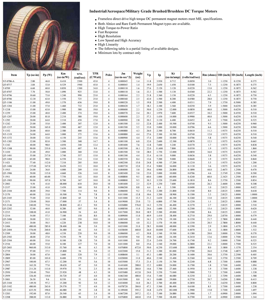
7-1 Maximum Rated Torque (TR)
It is the amount of torque that the motor can produce without danger of demag-netizing the rotor.
7-2 Maximum Continuous Stall Torque (TC)
It is the amount of torque produced at zero speed which results in a fixed Temperature arise.
7-3 Motor Constant (KM)
It is the ratio of the peak torque to the square root of the input power at Stall with room ambient temperature (normally 20-25C). KM = TP (Peak Torque)/√PP (Peak Input Power), or KM = KT (Torque Constant)/√RM (Term. Resistance)
7-3 Electrical Time Constant (t F)
It is the ratio of inductance LM in Henries, to the resistance RM in Ohms. This is the inductance and resistance as measured across any two phases in a delta or wye configuration.TE = LM/RM
7-4 Mechanical Time Constant (tM)
It is the time required to reach 63.2% of the motors Maximum speed after the application of constant DC voltage through the commutation electronics, ignoring friction, windage, and corelosses. TM = JM * RM/ KT*KB
7-5 Thermal Resistance (TPR)
It correlates winding temperature rise to the average power dissipated in the stator winding. The published TPR assumes that a housed motor is mounted to an aluminum heatsink of specific dimensions. Additional cooling from forced air, water jacketing, or increased heatsinking decreases the motor Thermal Resistance allowing higher power outputs than the published data.
7-6 Viscous Damping (FI)
It represents the losses in the motor which are proportional to speed with an in-finite source impedance. Such losses include windage, friction, and eddy currents.
7-7 Maximum Cogging Torque (TF)
It is principally the static friction torque felt as the motor is rotated at low speed. The published value does not include the bearing friction of a housed motor.
7-8 Design Voltage (VP)
It is the nominal voltage required to produce the peak torque when the rotor speed is zero and the winding temperature is 25°C. As such, VP is the product of IP and RM. At any temperature greater than 25°C, the required voltage to produce peak torque increases due to the increase in winding resistance. The design voltage is not a limit but a reference point for the data.
7-9 Peak Torque (TP)
It is the nominal value of developed torque with the rated current IP applied to the windings. For each winding specified the product of peak current (IP) and nominal torque sensitivity (KT) gives TP unless the maximum rated torque (TR) is reached.
7-10 Peak Current (IP)
It is the rated current used to obtain the nominal peak torque from the motor With nominal torque sensitivity (KT). IP is generally the design voltage divided by the terminal resistance (RM)
7-11 Torque Sensitivity (KT)
It is the ratio of the developed torque to the applied current for a specific winding. KT is related to the BEMF Constant KB.
7-12 No Load Speed (SNL)
It is the theoretical no load speed of the motor with the design Voltage applied.
7-13 BEMF Constant (KB)
It is the ratio of voltage generated in the winding to the speed of the rotor. KB is proportional to KT.
7-14 Terminal Resistance (RM)
It is the winding resistance measured between any two leads of the winding in either a delta or wye configuration at 25°C.
7-15 Terminal Inductance (LM)
It is the winding inductance measured between any two leads of the winding in either delta or wye configuration at 25°C.
7-16 Rotor inertia (JM)
It is the moment of inertia of the rotor about its axis of rotation.
7-17 Motor Weight (WM)
It is the weight of the standard motor.
7-18 Number of Poles (NP)
It is the number of permanent magnet poles of the rotor. For the standard HT Series motors this ranges from six to twelve poles.
7-19 Speed-Torque Curves
HT Series curves are for the standard catalog designs. The curves are based upon a 75°C rise over the ambient temperature. HS Series curves are for the designs which substitute high efficiency laminations to allow operation at higher speeds.
8、Torque Motor Order needed Information
E-mail: hktoptech@toptechelectric.com
Website: www.toptechelectric.com
